A daunting task, and one I am looking forward to completing. As the replacement parts (purchased from CJ Pony Parts) have yet to leave the U.S. , I decided to get started by removing the front end.
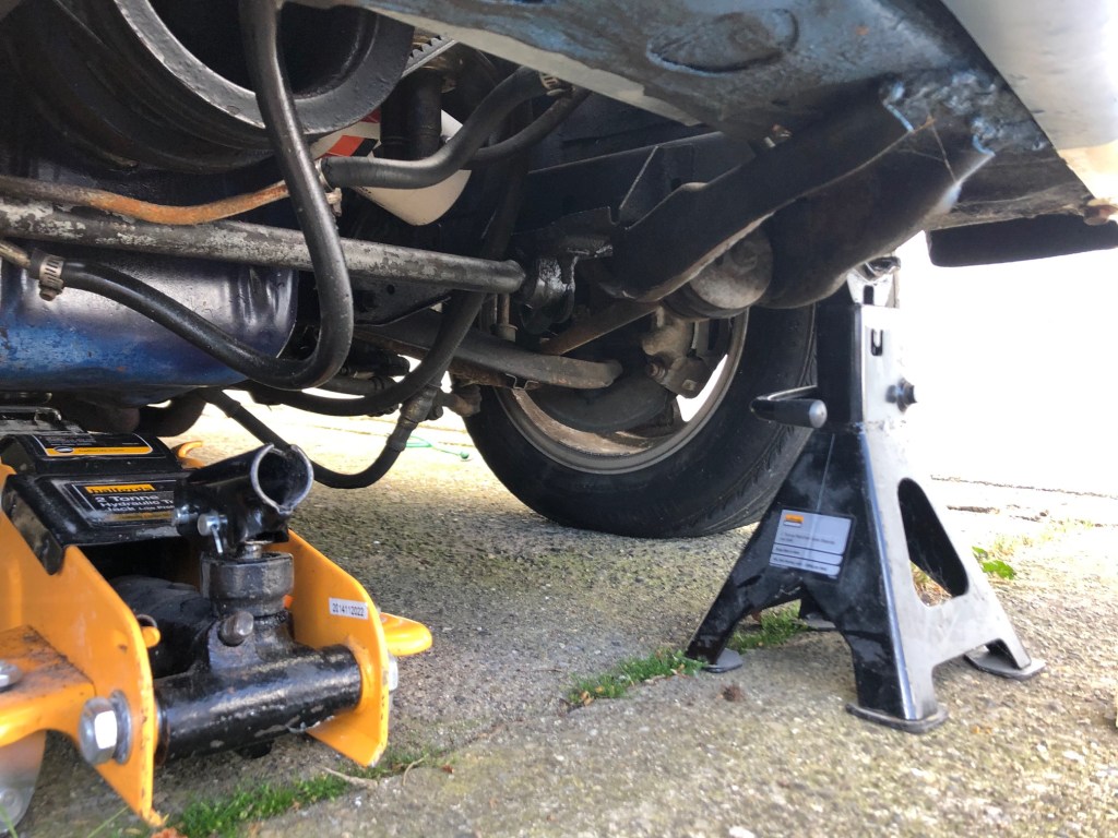
My first dilemma was to determine where axle stands could/should be placed, especially as the car could be like this for a few weeks. After consulting the folks on the Vintage Mustang Forum site, I went with setting the axle stands on the front frame rail, just back from the valance. This should provide a better ‘balance’ than the usual jacking point option, rear of the front tyres.
I prepared by setting the axle stands at the height I wanted and by cutting two pieces of wood to place on top of the stands for the frame to rest on. I loosened the wheel nuts and then jacked the front of the car up (making sure to chock the rear tyres first) via the cross member. The cross member on my car has seen better days and needs replacing but that’s a job for another time.
Once jacked up, I moved the axle stands into position, removed the wheels and let the car slowly down. So far so good!


The next job is to remove the shocks, which I installed 5 years ago.
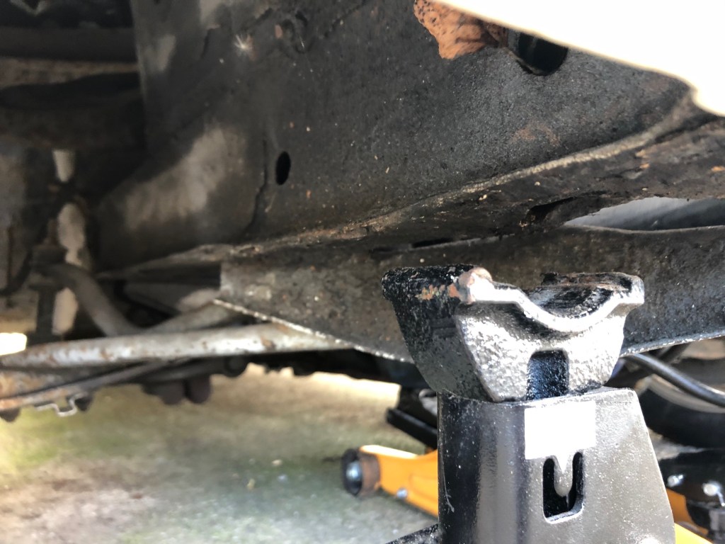
After worrying overnight about the car being on axle stands, the first thing I did was cut some timber and place it under the frame at the usual jacking point. A little bit of extra safety!
Then I had a bit of a ‘duh’ moment. When researching the best way to approach removing the springs I had seen a number of comments stating that you should remove the top shock bolts before jacking the car. So, I put the wheels back on, lowered it, undid the top shock bolts, jacked her up, removed the wheels and placed the axle stands..again (Good practice).


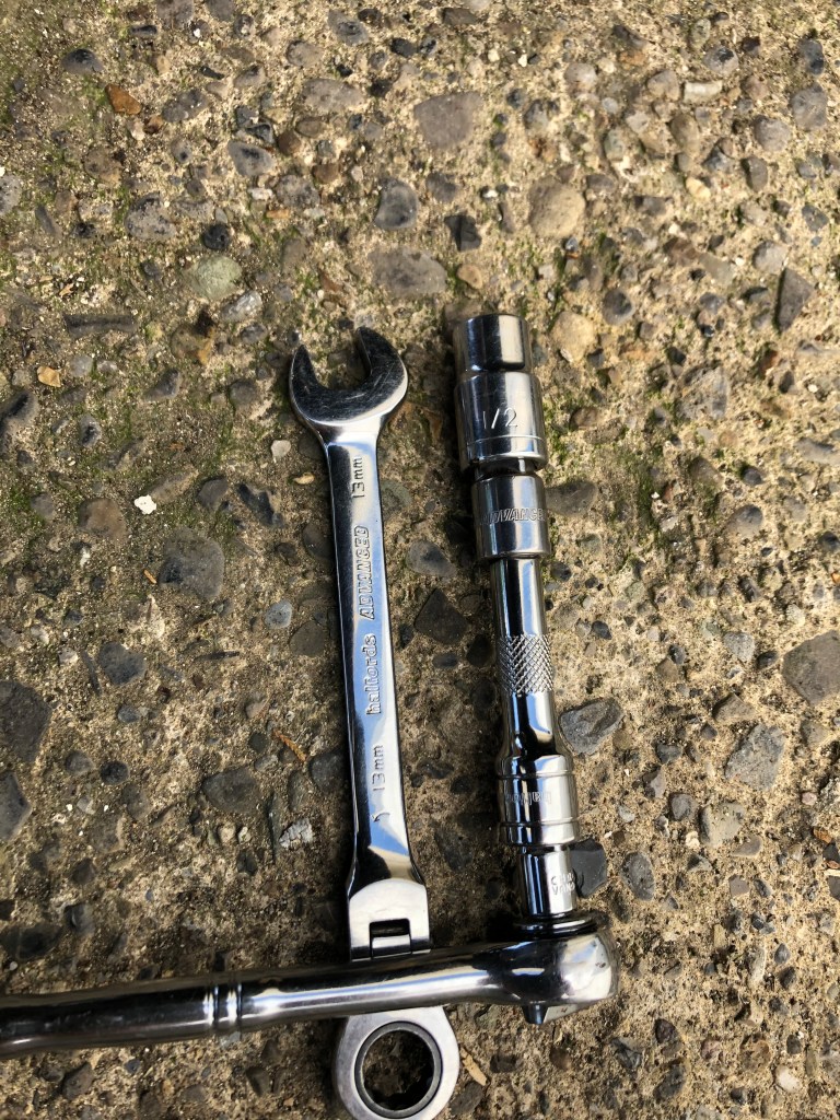

Thankfully the bottom shock nuts (which go through the spring perch) were not that difficult to remove as they had only been on the car 5 years. I remember it being a major pain when I first did it as the nuts were rusted solid. I used a 13 mm spanner on the front nut and a 1/2 (just because I couldn’t find the 13mm socket) with an extension for the rear. I made sure to keep all the mounting hardware as I’ll be using them again. With all the bolts off, you can remove the shock through the top without too much trouble.
Now it was the tricky and potentially dangerous job of removing the spring itself. Unfortunately there is a lack of photographs here as I was just trying to get it done as fast and as safely as possible.

FIg 1 
Fig 2 
Fig 3 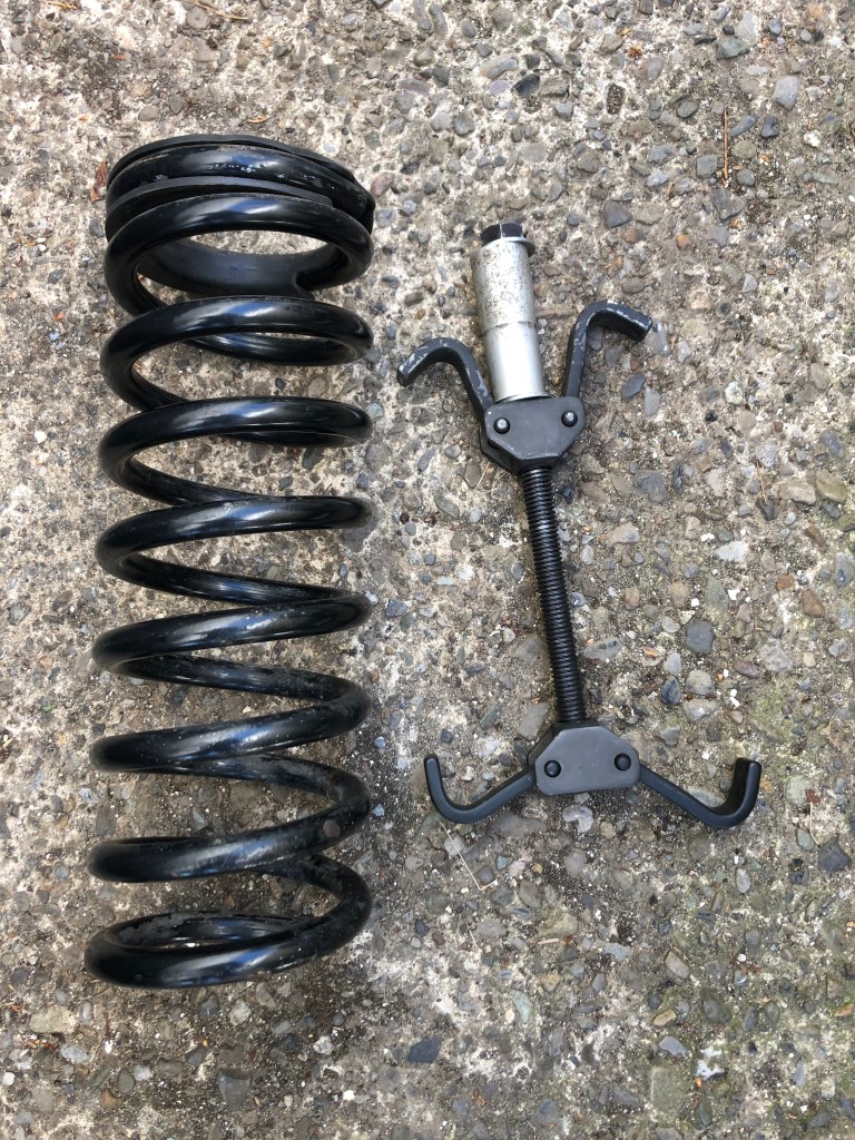

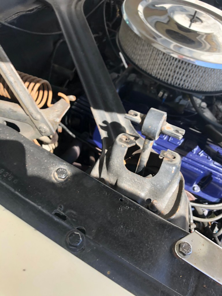
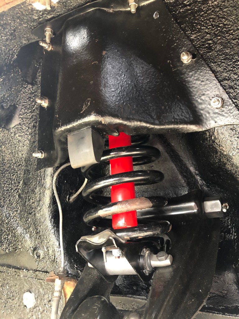
Before starting to remove the spring, you need to remove the inner shock tower guard (You can see it in place in Fig 1 and removed Fig2). You will probably need two 13mm sockets/wrenches so you can keep the nut from spinning inside whilst you undo it inside the engine bay. A bit hard on the body, but got them off without too much trouble. I’m going to reuse these so will give them a new lick of paint before they go back on.
With the guard removed the full spring is now visible (Fig 3). Just a reminder that this is a VERY dangerous job so think long and hard before attempting this yourself if you are even the slightest bit unsure of yourself..and even if you are!
The aim was to remove both wheel hubs, control arms, sway bar and strut rods. Expectations and reality do not always align…
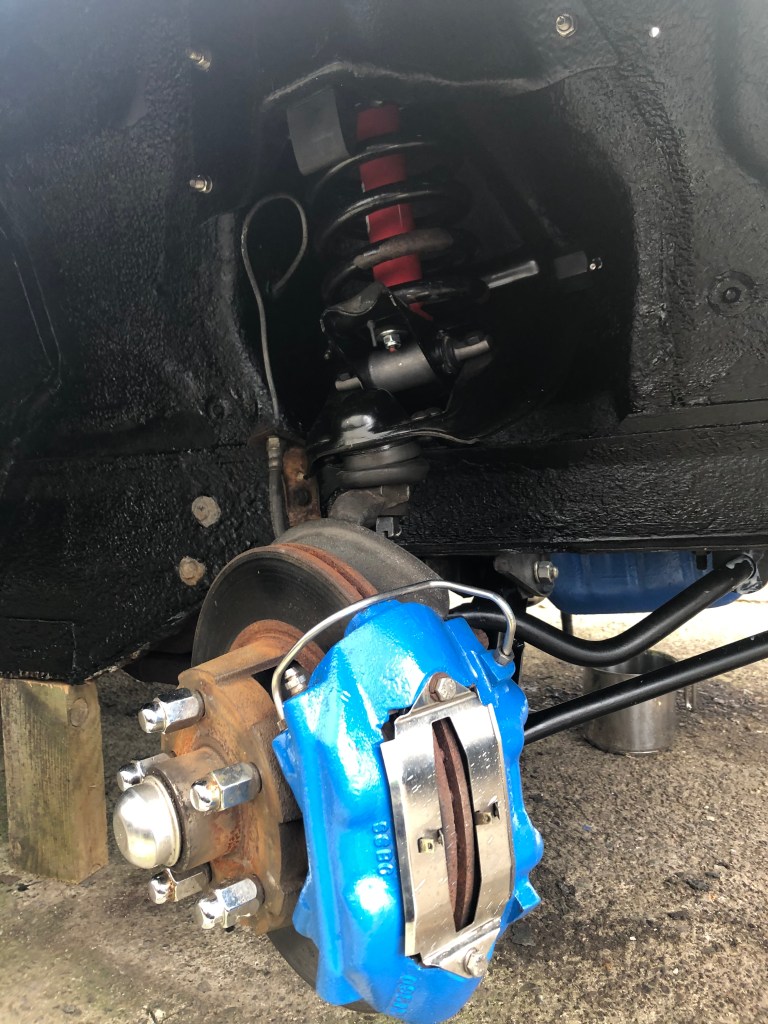
I started on the passenger side, recognising the first thing I needed to do was disconnect the brake line. Unfortunately it refused to disconnect where the rubber brake hose meets the brake line (Fig4), but I was able to undo the connection where the brake line connects to the disc brake housing (Fig5). The problem I had was that it was impossible to undo as the rubber hose was trying to tie itself in knots. The solution was to remove the entire brake caliper and then undo the brake line (Have an oil pan or similar ready to catch the brake fluid)

Fig4 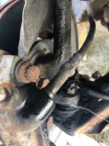
Fig5 
Fig6 
Removing the brake caliper is done by undoing two bolts, connecting it to the wheel spindle. You don’t need to undo the two smaller bolts, which connect each half of the caliper (These are SSBC 09516 – pretty standard for the era). With the brakes off, I moved on to the ball joints.

Fig7 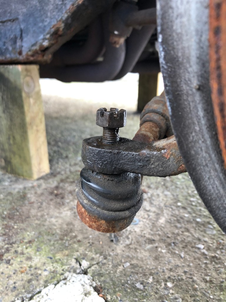
Fig8 
Fig9 
Fig10
I started with the tie rod (Fig7), which, after removing the cotter pin, came loose pretty easily (Fig8). I had picked up a ball joint separator (Fig9), not a pickle fork…although these parts are not going to be re-used, but it’s too small for anything else than tie rod connections. It popped loose pretty easily (Fig10)
Next was the upper control arm ball joint (Fig11). After removing the cotter pin, I was able to crack it loose, threading the nut down until it was only just on. I then hit the side of the ball joint 3 times with a mallet, which popped it loose (I’m told this hardly every works…but worked very well for me on both sides). Keeping the nut on the bolt by a few threads stops it hitting the ground & me. I then did the same for the lower control arm ball joint. This one was a bit more stubborn, and as I am not reusing these parts, I resorted to hitting the bolt 5 or 6 times, which did the trick. I then removed the upper control arm nut (Fig12) and pulled the disc/spindle off the car (Fig13). The same process was repeated on the driver side.

Fig11 
Fig12 
Fig13
It was now I turned my attention to the sway bar end links and strut rod. As you can tell by the pictures, this hardware is in a sorry state. The mounting hardware for the strut rod was mostly rust and the end link nuts weren’t much better. I decided to give them a liberal soaking of WD-40 (I know there are better products for this type of thing, but I don’t have any).
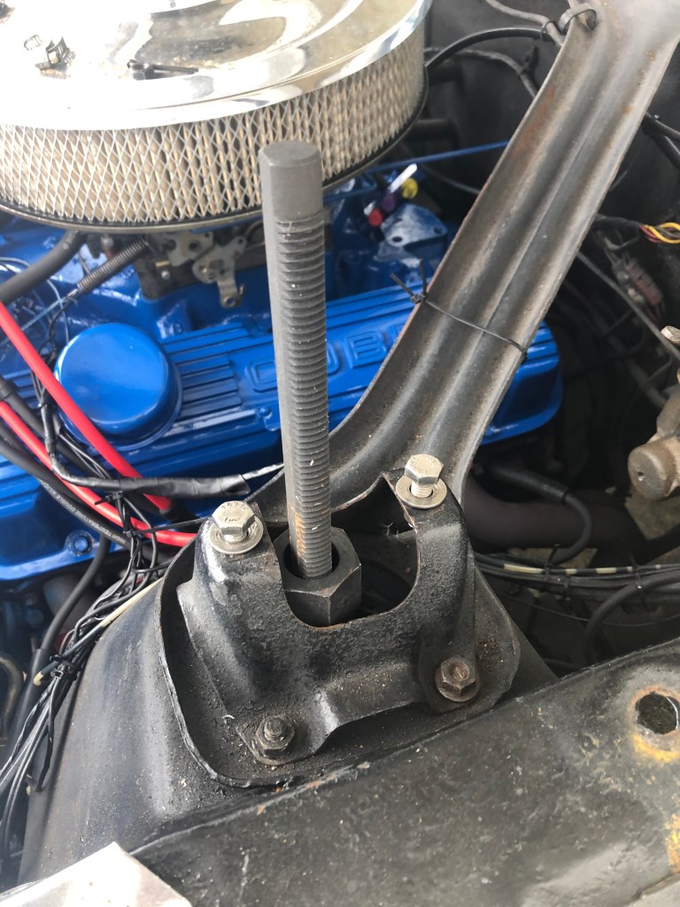
I started by loosening the nut on threaded section of the strut rod (7/8’s). Note: This would be made easier if I had a 10 inch socket extension. After a bit of a battle I was able to remove the nut and the washer (Fig15). Then I moved back to the two bolts securing the strut rod to the lower control arm. The WD-40 had worked its magic (I think) and I was able to remove both (Fig16) although I did have to use two socket wrenches (One to undo the nut (18mm) and one to stop the top of the bolt from spinning (16mm). I was then able to pull the strut out. Note – The strut rod spindle stop is a separate piece connected by the same bolts. You can see this top right of Fig17

Fig14 
Fig15 
Fig16 
Fig17
I’m not replacing the strut rod, but I am replacing the bushing, so I will be cleaning this up ready for re installation.
The next step was to remove the Lower Control Arm itself (Sway Bar end link removal is covered here). Using the 7/8 socket and additional leverage of my handy extension bar (an old piece of exercise equipment!) I was able to remove the LCA bolt easily (Fig18), only to find that the bolt would not come out as it was blocked by the crossmember (Fig19). I was really worried about trying to remove the crossmember bolts as I’d read horror stories about the fixed nut (inside the chassis rail) breaking. I was particular worried about the driver side as it was obvious there had been some major repairs at some point in the cars history. Thankfully the passenger side bolt came out ok (Fig20) and I was able to then remove the LCA completely (Fig21) but only because the crossmember moved out of way…far to easily (Fig22).
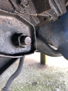
Fig18 
Fig19 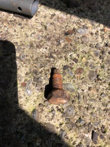
Fig20 
Fig21 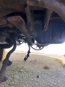
Fig22
The bushings on the LCA were completely shot. The only piece of this I’m re-using will be the LCA bolt.
My worst fears were realised when I tried to loosen the driver side crossmember frame bolt. A horrible grinding noise and a freely spinning bolt. I was able to put my finger on the top of the bolt inside the frame rail and it was indeed spinning. I was contemplating buying a reciprocating saw to cut through the bolt, but decided to see if a bit of pressure on top of the bolt would help. Pushing down on the bolt with the end of a screwdriver resulted in the bolt and nut popping loose!
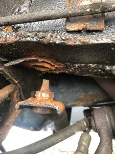


As you can see by the pictures above, it appears the bolt had once been welded into the hole (presuming an old attempted fix). The really worrying thing is that I had jacked the car up using the crossmember meaning the entire weight of the car (on the driver side at least) was just sitting there. It’s not worth thinking about. Now that this is out of the way I can continue to remove the strut rod, sway bar end link and LCA. Fixing the crossmember bolt will be left until after all the new hardware is installed.
Try as I might I could not separate the LCA / Strut rod bolts loose, therefore I decided to remove them both as one unit so I could work on them on the bench. After considerable effort I was able to separate the strut rod from the LCA. Take a look at the state of the LCA bushing (Fig23).
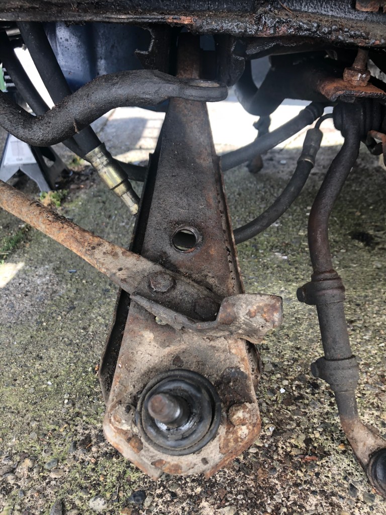


Fig23
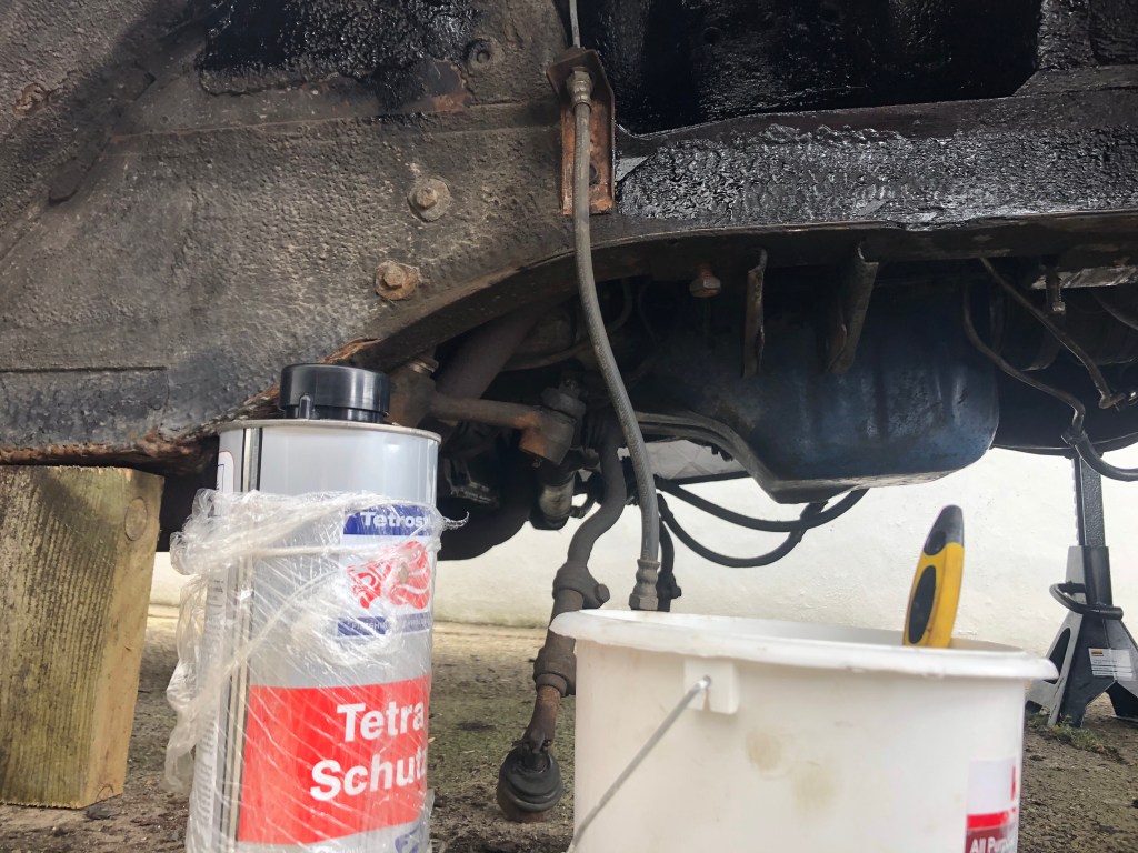
Now with all the parts out of the way I started cleaning up the area ready for a coat of underseal. Years of dirt, grease & old underseal made it hard going, but a stiff wire brush and a putty knife did the trick. I used a vacuum cleaner for the top of the frame real, which sucked out quite a lot of dirt. I had purchased an underseal gun to use with my compressor but read that you can also apply it by paintbrush, which is a lot less fuss and mess. I wore eye protection and a face mask to be safe. Each side took 45 minutes and it was dry within 2 hours.

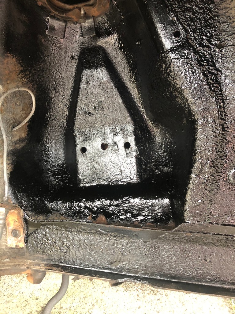
Passenger side 
Passenger side 
Driver side 
Driver side
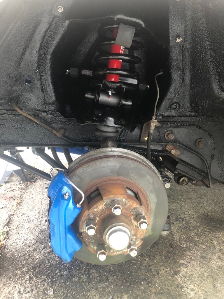
With the paint dry, I was able to test fit the UCA & LCA on the passenger side. Everything fit well, which is great so I transferred the shims from the old UCA and bolted it and the LCA in place, although I didn’t tighten it to the required torque spec as I read that you should do that with the car on the ground. I installed the strut rod (Interesting note is that the replacement bushing kit has the washers installed ‘backwards’ – which is actually correct.
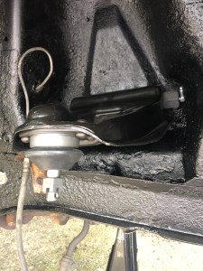


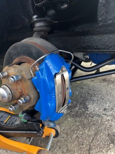

Fig24
I then used the trolley jack to hold up the LCA whilst I reinstalled the spindle, connecting it to the tie rod and upper & lower control arms. The newly painted brake cylinder was then reinstalled to complete the passenger side (Fig24).
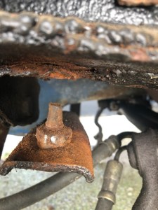
The driver side went well until I went to tighten the outer tie rod to the spindle. The bolt spun (which it should) but I found that the cap was loose and full of dirt (Fig25). Although it will delay getting the car back on the ground I decided the best thing is to replace the outer and inner tie rod on the driver side. The parts were ordered from CJ Pony Parts so I have a week or so to wait.
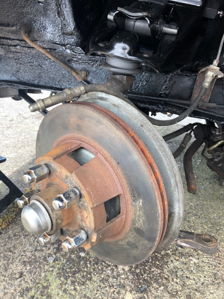

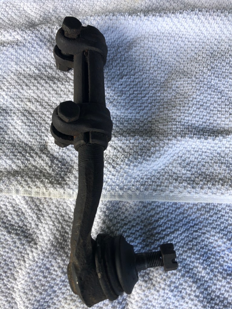

Fig25
The new inner & outer tie rods arrived on a Friday, which was great timing for the weekend. I went to remove the inner tie rod but it refused to come out. I resorted to hitting it on the bolt but all that did was mushroom the bolt (fig26). I finally decided I needed a pickle fork to remove it so I had to wait a few days for it to arrive. Once it did, I gave it two hits with a mallet and it was loose but I couldn’t remove it because I had mushroomed the bolt. I used a file to get it to the point it could be removed (lesson learnt).


Fig26
Once removed I assembled the new inner & outer to be the same length, tightened the sleeve nuts and installed it on the car.
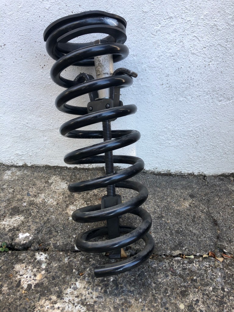
At this point I was able to look at reinstalling the coil springs. But I lose my nerve (and patience) using the 4 hook compressor. I did some research and found that there was an alternative, safer option. The issue is that the tool is not cheap but I decided to purchase it due to the safety benefits. For those that are interested here is the link I used to purchase it – here.
It took a week to arrive but I had one of the springs back on the car in 15 minutes!! – Faster and safer. The new shocks went in next (Scott Drake) and then the shock tower guards. Finally after a month, the car was getting close to being on the ground.


At this point I decided against jacking the car up via the cross member, choosing instead to jack the passenger side the few inches needed, via the standard jack point, to mount the wheel. Once done I jacked it a few more inches in order to remove the jack stand. Then did the same for the driver side. The car is finally back on the ground!
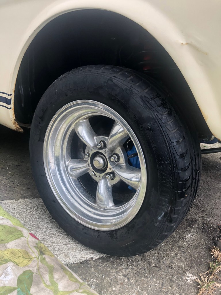
Mounting the wheel 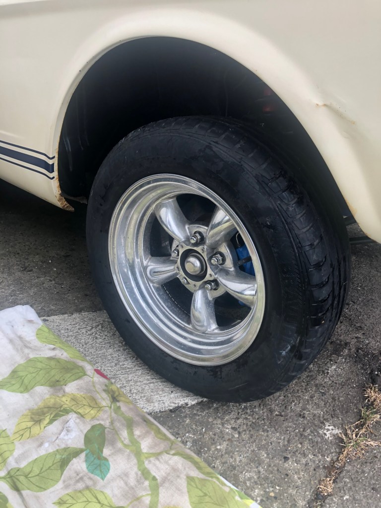
With the driver side still on the axle stand 
Finally on the ground after a month up in the air
I then torqued the lower control arm bolt to the required spec (75-100). Job done!
